Disclaimer - I'm writing this blog post about an year later after the internship, so I might have missed few things. Kindly contact me if you need further information. This post, in no way, gives the full information for building a 3D printer yourself. It is just for documenting my internship experience. If you do not wish to read the entire post, you can look through my notebook which should give you a fair idea about we did.
Prelude
I did my sophomore year summer internship at one of the budding Delhi-based startup named 'DreamsInfinity'. It was a product development internship meaning I was hired to build a commerical 3D printer based on UV-DLP (Ultraviolet Direct Light Processing) technique which was a new concept introduced in the world of additive manufacturing at that time. This post aims to describe what we did and what we came up in the end.
Selection Process
I applied for the internship on Internshala somewhere around May. I had another internship planned initially but it was related to web development. I had to work on WebRTC and it could have been exciting too but I was always inclined towards industrial design and getting a chance to build 3D printer in sophomore year was just too good a chance to pass. By the time, I appeared for the telephonic interview after the initial screening (based on general questions and resume), there were already around 250 applicants.
I think my E-cell & robotics club experience came in handy here. In internship description, it was explicitly said that the interns should be able to work with minimal guidance. My mentor, Mr. Anubhav Bansal, worked in his family business as a business development head and this was his side project. So, you can say that the startup was in its infancy.
Anyway, 2 people were selected for the internship - me and one guy from NIT Allahabad from Electrical & Electronics department. He was in 2nd year of study as well.
The Beginning
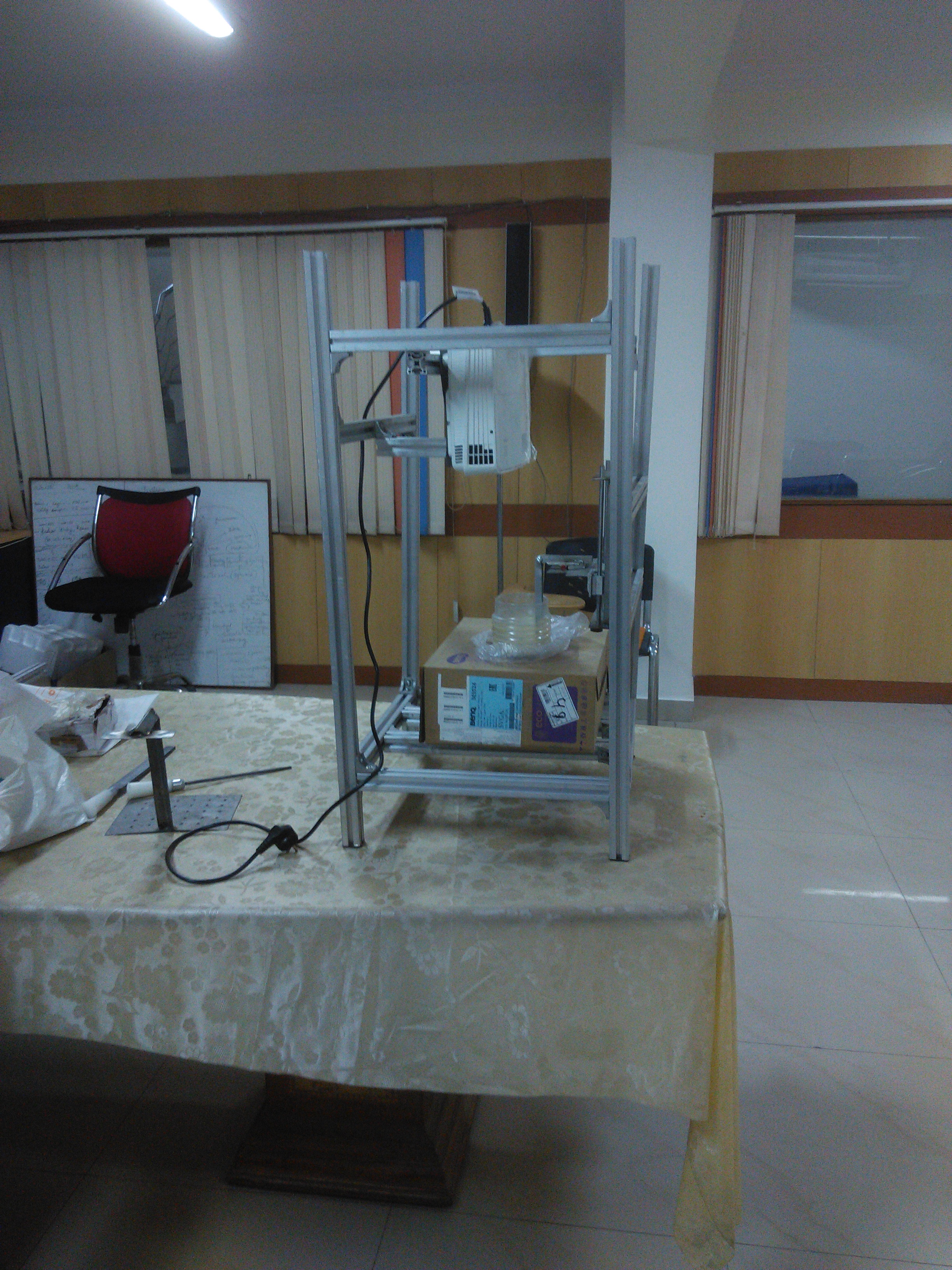
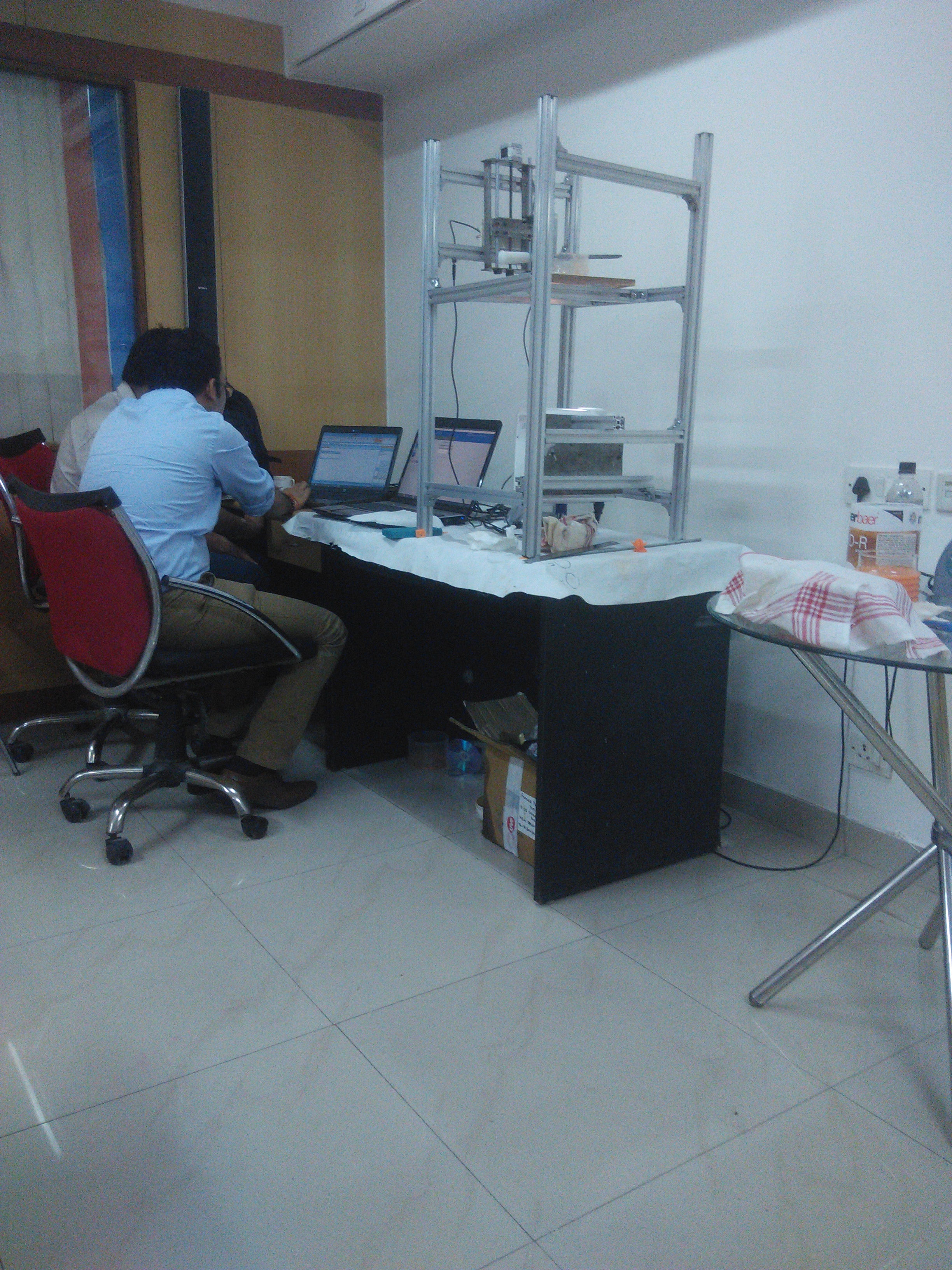
On our first day, we were taken to the basement of a building which was going to be our maker room. My mentor had been working on the basic skeleton as a proof of concept for 3D printing. It looked something like -
We started with reading the documentation of various 3D printers available in the market.
At that time, the majority of 3D printers available were based on FDM technique which is still the case but we wanted to work on UV-DLP technique for several reasons -
- We wanted a cheaper, affordable 3D printing service for mass market
- Our initial target audience were those of ornament shops, shoe design companies, etc. We wanted to give that soft material material feel.
- No hassle of base plates
- fast printing time and the ease of print
- Using open-source 3D slicer that read STL files
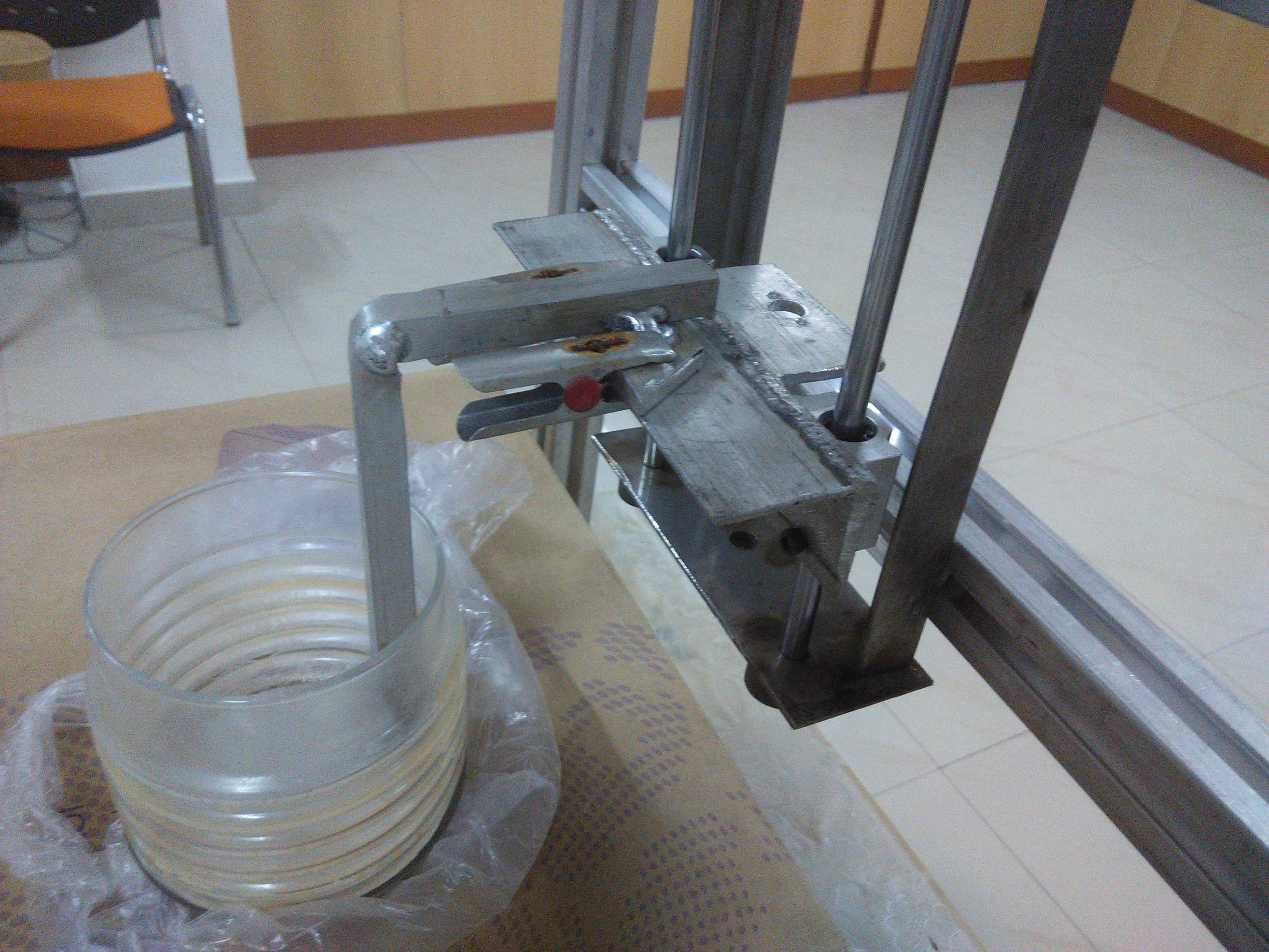
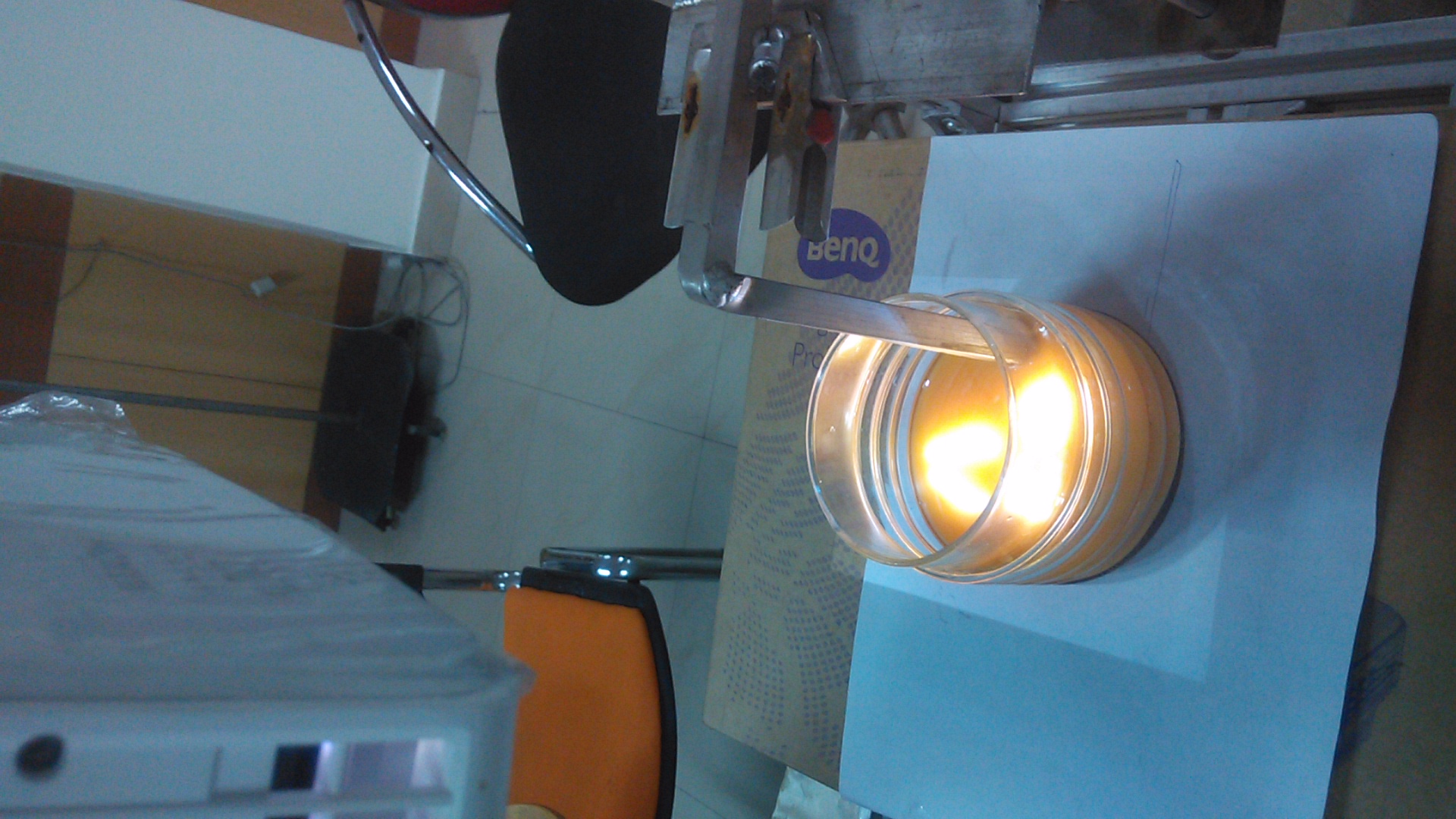
First of all, we had to get the basic ingredients right and find out if we can actually make the 3D printing work. We had some basic T-slot aluminium extrusion frames, L-clamps, unipolar stepper motor, lead screw, general projector (for projecting 2D slices intermittently) and a crudely welded base plate, plastic container, photochemical resin, resin hardener OPV 7102 and a UV light source to harden the model after printing.
We quickly started putting up a crude model together. We downloaded 'Creation Workshop' software, which is basically a slicer program for DLP 3D-printing, built up the circuit on a bread-board using following components -
* Board - Arduino Micro
* LCD - 16x2 4-bit Mode
* Motor Driver - A4988
* Potentiometer (to set the contrast ratio of LCD)
* Capacitor (used with motor driver)
* Jumper wires for the connections.
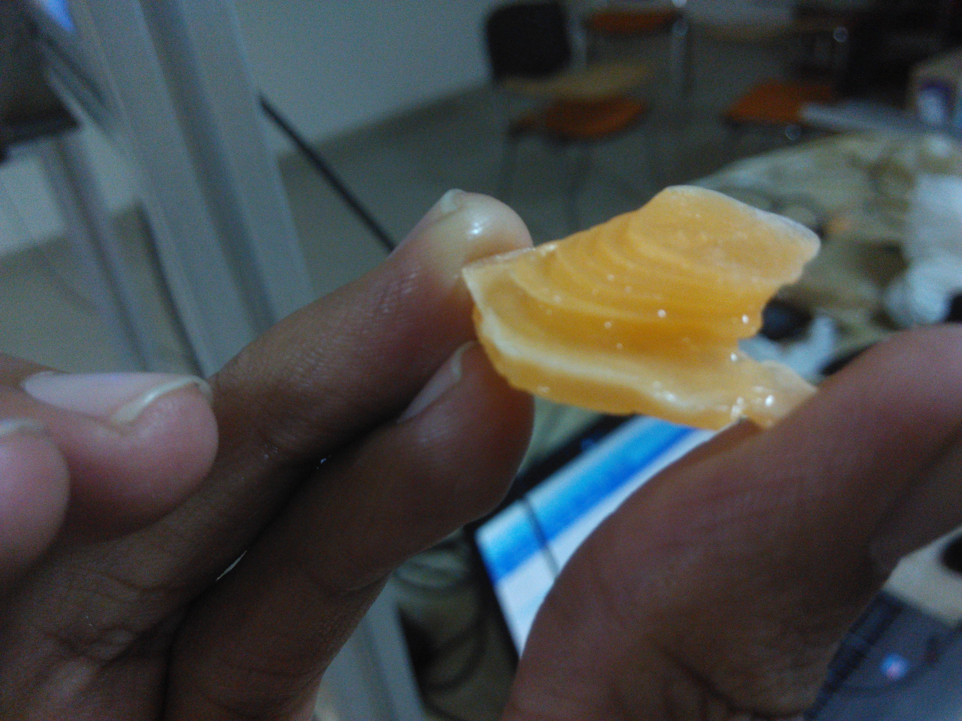
The basic skeleton was ready and we were set to print our first models. Contrary to our surprise, our first few models looked like this -
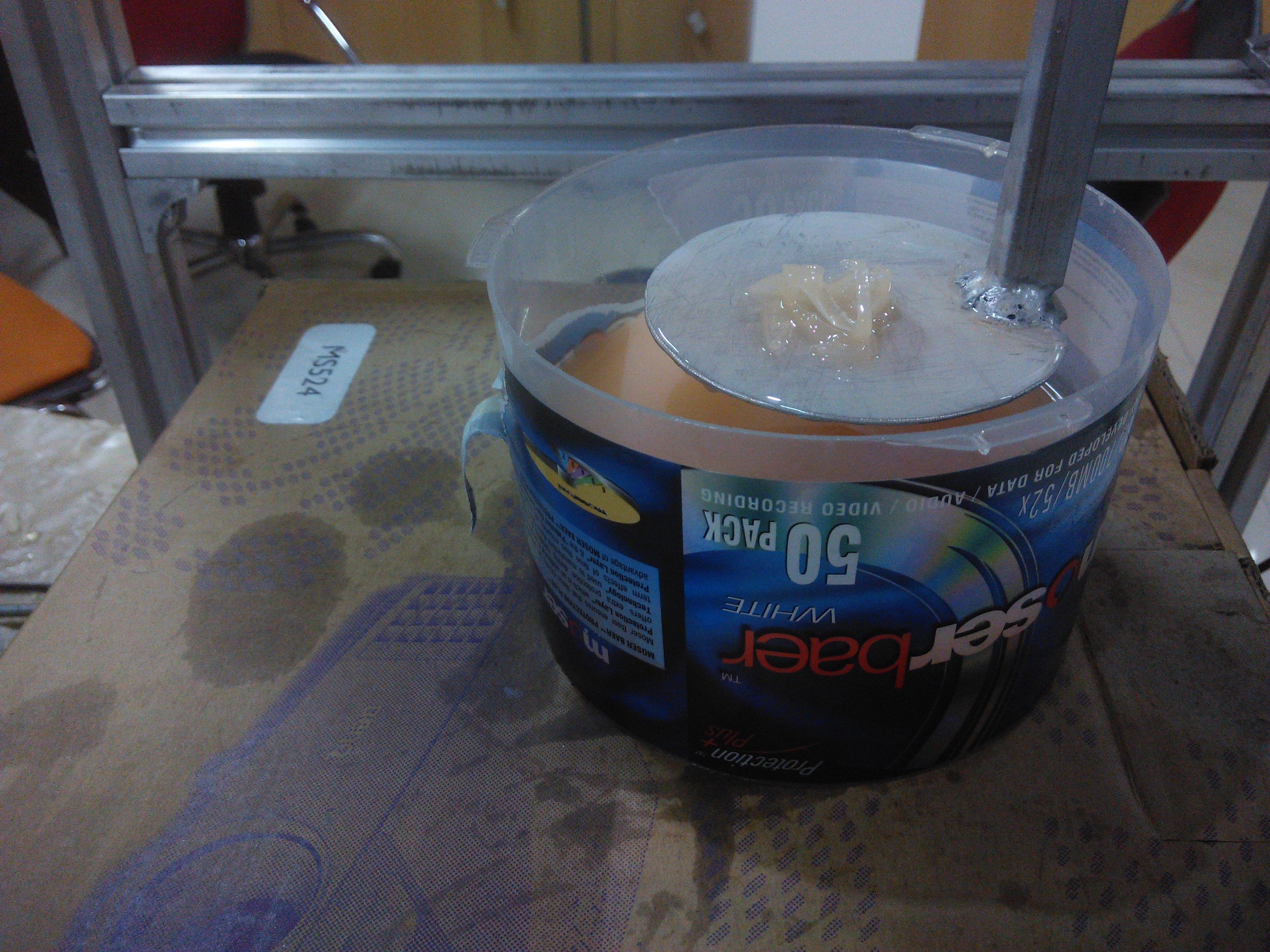
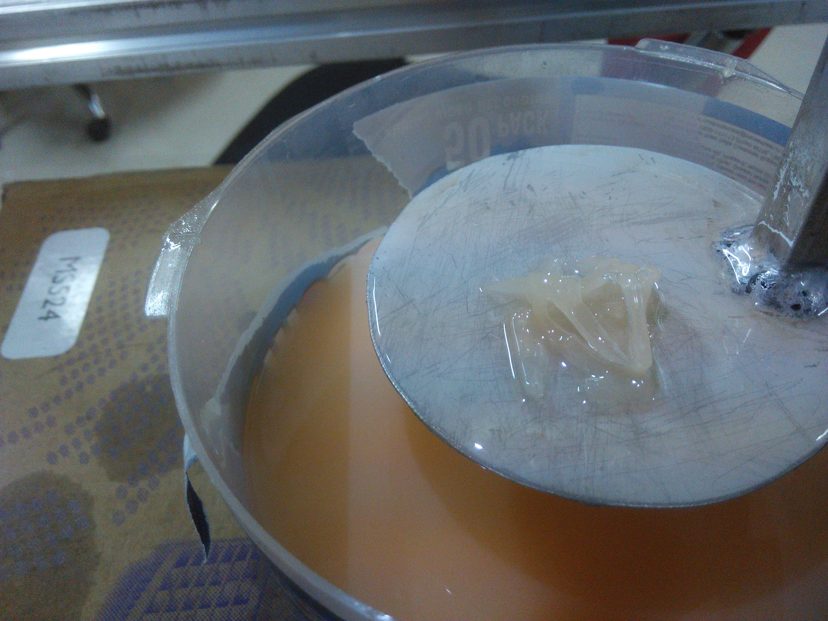
Hmm...not quite what we want.
The Battle
Ok, let's take it bird by bird. So what are the variables here?
- Projector
- Resin
- Priting variables
    - Slice thickness
    - Exposure time
    - No. of bottom layer
    - Retract speed
    - Lift speed
Projector specifications - We kept the luminosity of the projector at 3200 lumins and resolution at 800x600. The only variable here was the distance of the base from the lens for optimal printing quality. Since, we didn't have any other projector at disposal, we had to work with what we had. Later on, we searched for the best projector for the purpose and settled on InFocus IN8606 HD projector.
Trivia You Should Know

- With DLP projection, printing speed is not affected by the object complexity or the number of parts to be printed on the same base.
- Wall-thickness(the minimum thickness that your model should have for any given material or technology) should be increased as the design becomes larger :
    if (∑(x,y,z dimensions) <= 200mm) wall_thickness = 1mm;
    else if (∑(x,y,z dimensions) ϵ (200 400]) wall_thickness = 2mm;
    else wall_thickness = 3mm;
- Orientation of the design while printing influences the surface quality and strength
- Model needs to be supported externally to keep it in place and prevent from collapsing while being printed if it is narrower than 30 deg.
Resin - This is where we spent most of our pre-fabrication time. It was absolutely essential to get the resin quality right (composition of resin & hardner). We also injected color for different model varities. The transparency of the resin is also something we had to take into consideration. Since it is photo-sensitive, greater transparency meant the light from the projector would affect the liquid beyond the active layer.
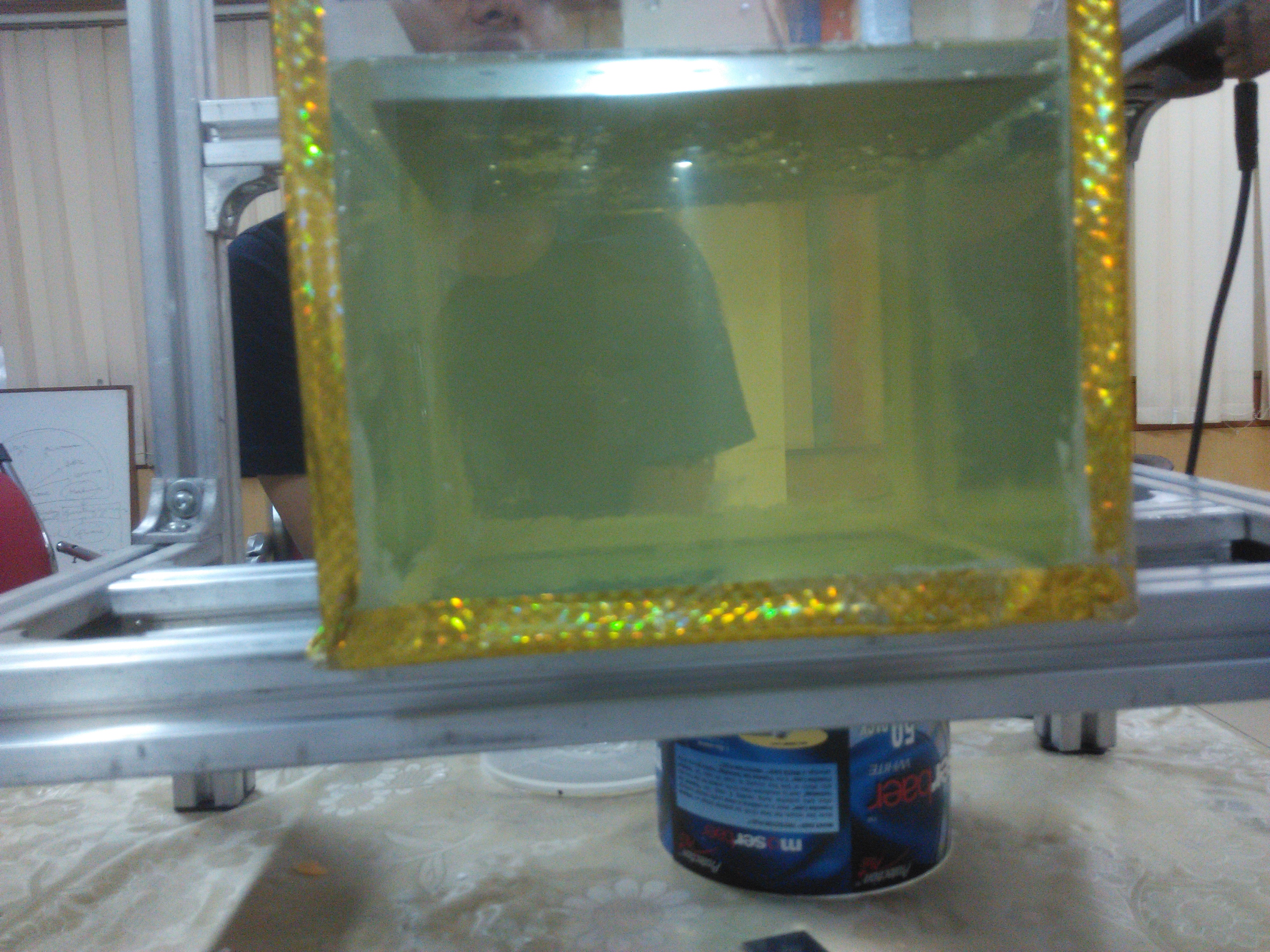
Printing variables - As is evident from the notes, we did a ton of experimentation on each of the aforementioned parameters, both in top-down and bottom-up approach (more on it later). We finally arrived at the numbers which would give the best printing quality and modified the open-source code accordingly.
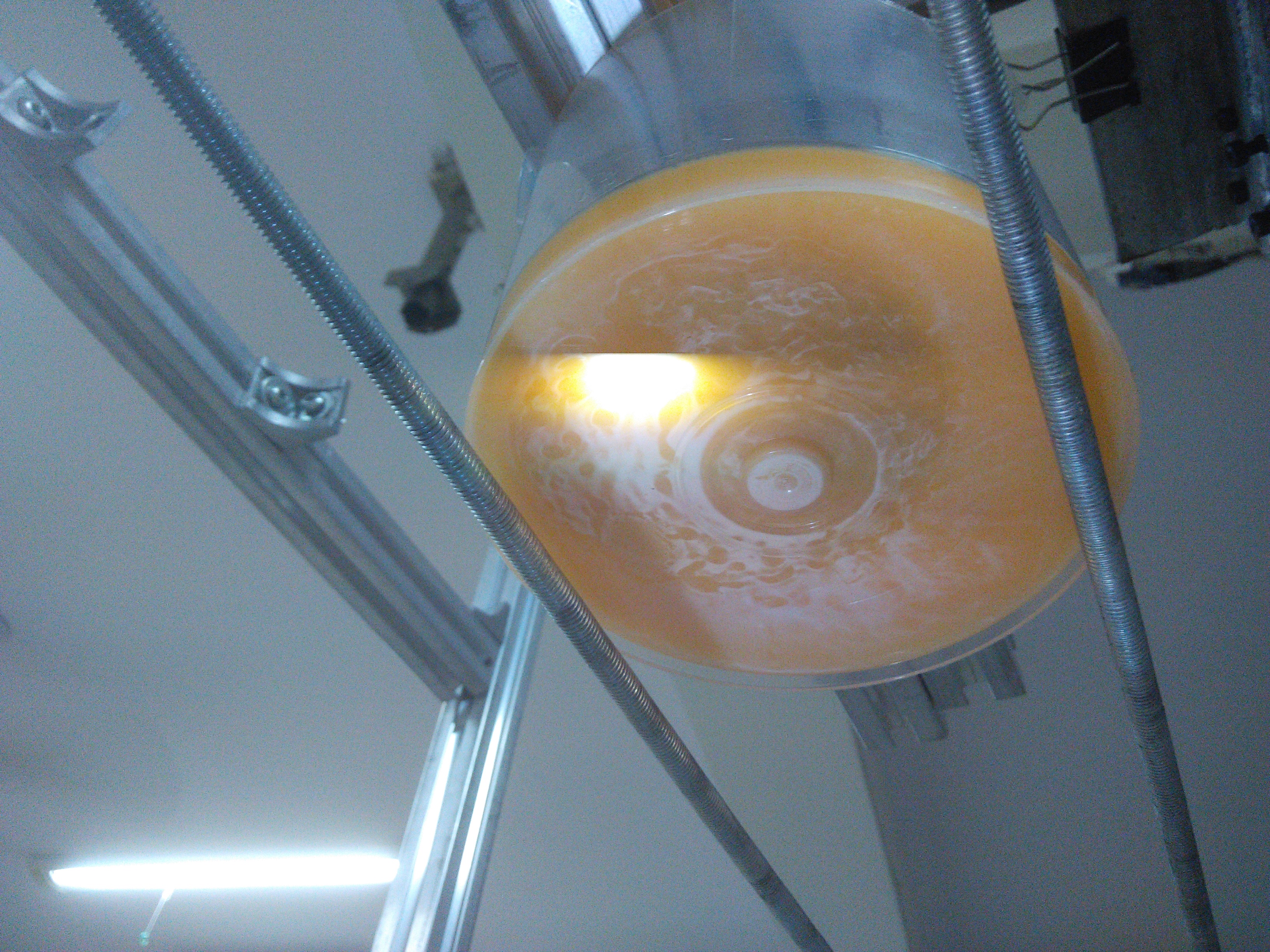
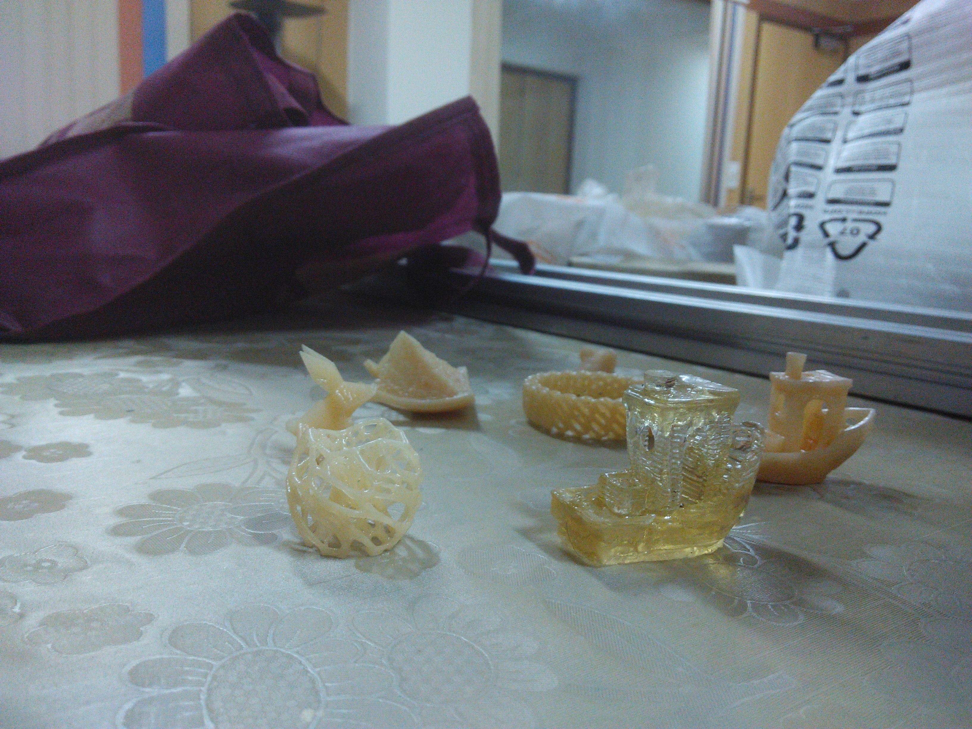
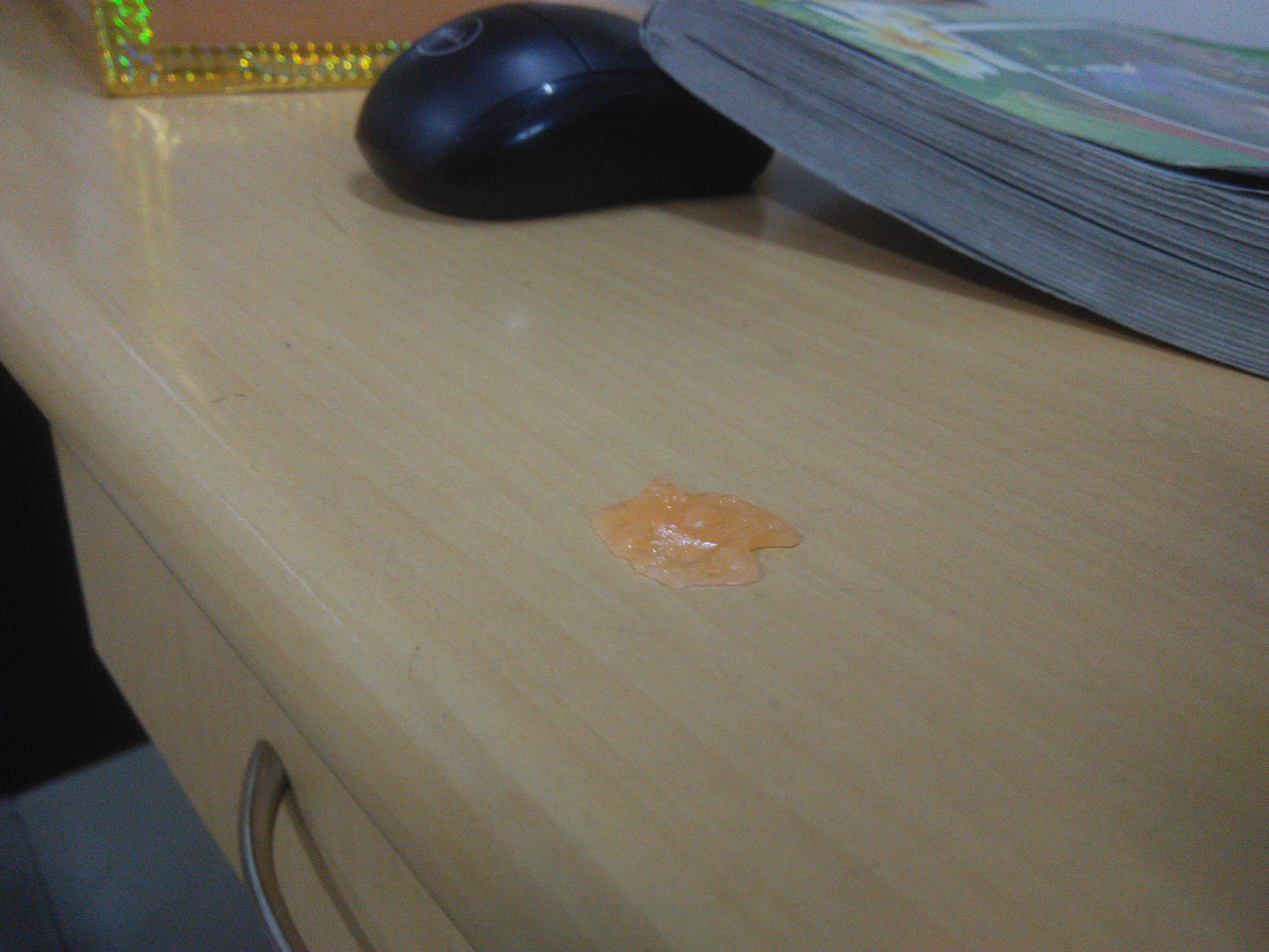
After tackling these problems, we started getting some pretty good print qualities -
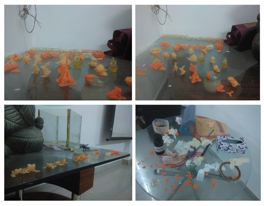
We printed a lot of these models. I mean a lot.
It was time to give it an aesthetic form which meant going back to the drawing board and redo everything from scratch (now that we have figured out the functionality). I have broken down the next phase into four different parts -
- Mechanical Design (*crude* sketching, CAD modeling, drafting)
- Manufacturing & Assembly (parts procurement, vendor identification, shop visits)
- System Design (basically electronics and other electrical hardware components)
- Code (customizing 'Creation Workshop', writing our own arduino code for motor movement)
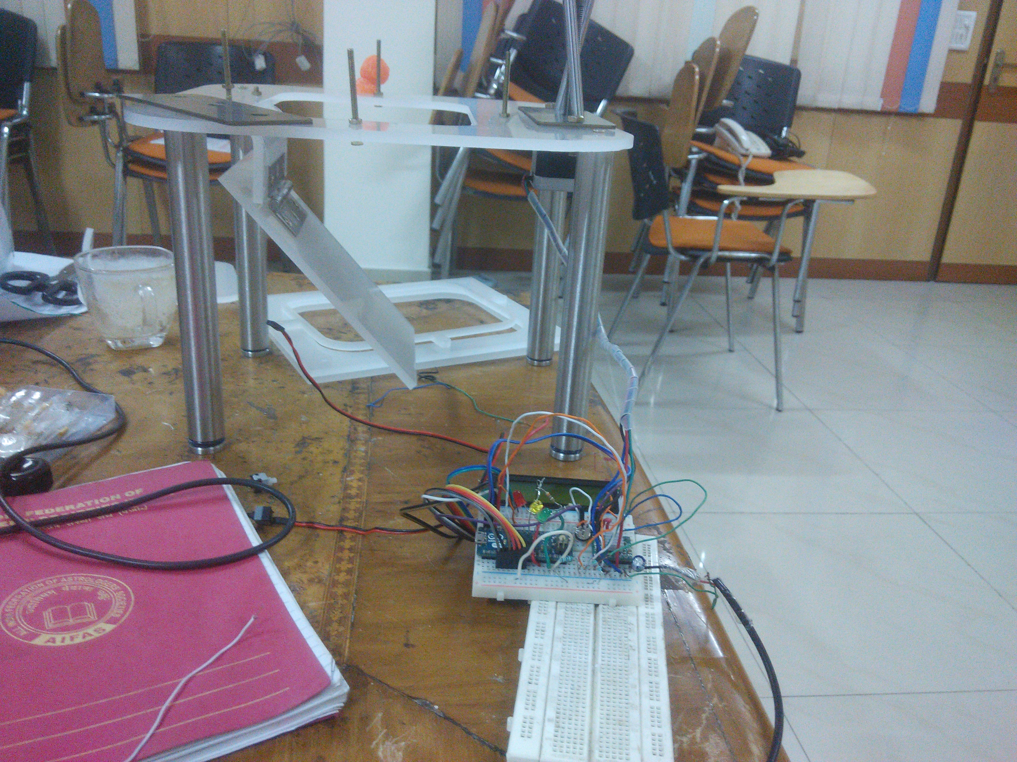
Before we move ahead with the topics, here are some of the design features we finalized for v1.0 -
* Flexible vat size
* Cover lifting mechanism
* Projector to be kept horizontal to reduce vertical height (use mirror)
* LCD Screen
* On-off button (zero position setting)
* Alternate mechanism for resin to settle in bottom-up approach
* Sensors to trigger when the vat reaches extremes
* Alignment balancing
* LED indicator
* Resin filling (Automatic & graduate)
* Overall cover
* Material selection (resin can be reused after melting)
* Color injection
* Immiscible (heavier density) fluid to reduce resin requirement in top-down approach
* Reverse movement of the base to maintain liquid flow
* Feedback control
* Base position marking (static base positioning to avoid fluid sloshing)
* Opening for venting smoke
* G-code & M-code interpreter
* Adapters for motor, arduino board, etc.
* Speed variation with changing slope
* Increase time exposure for smaller or finer area
* Third-party feature integration to let users browse 3D models online
Mechanical Design
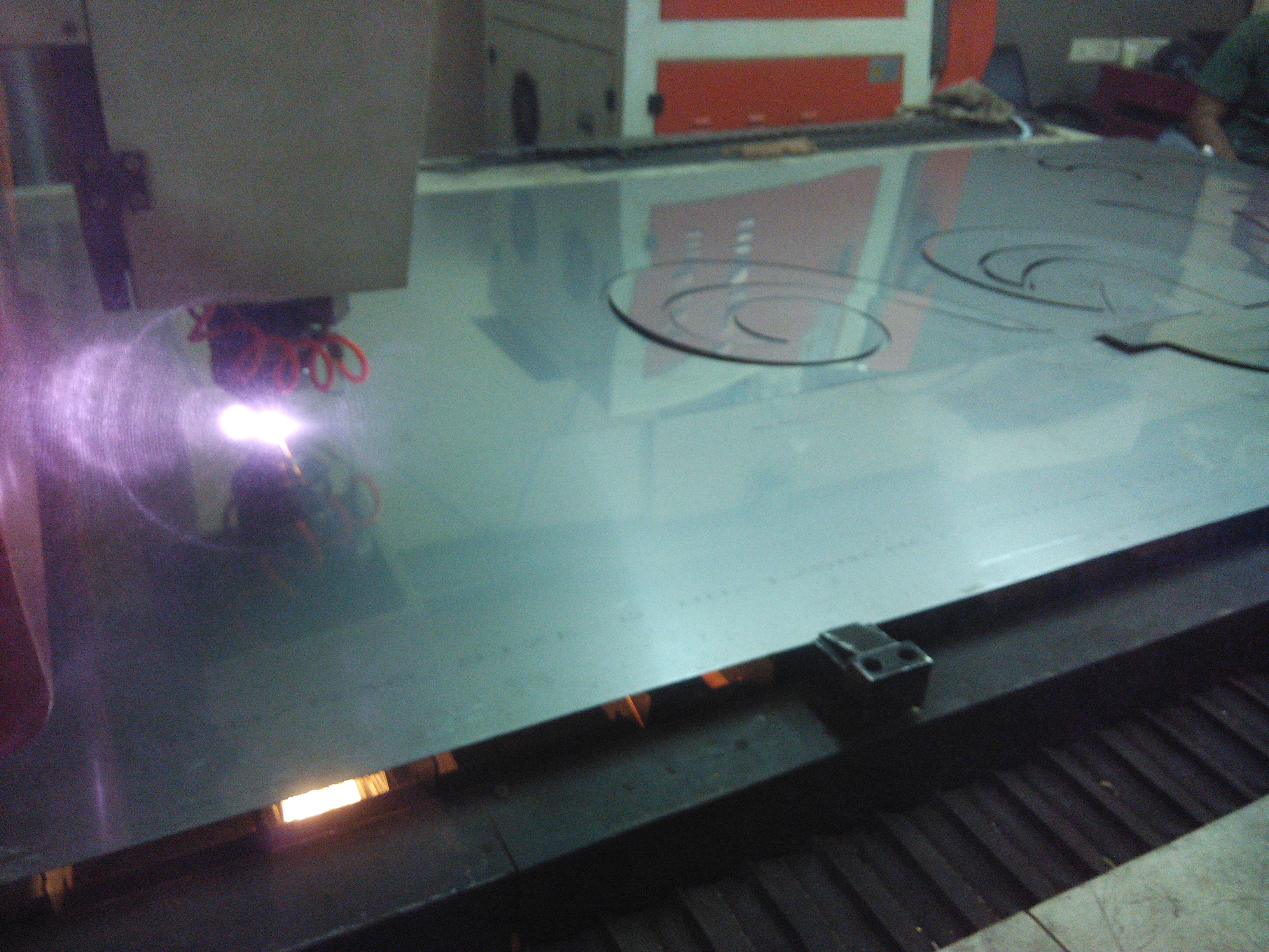
Based on our requirements, we decided the dimensions and made the 3D models in Solidworks for both top-down and bottom-up approach separately. Individual components can be found here. For sketches, please refer to the notebook at the end.
We exported the .dwg files for laser cutting.
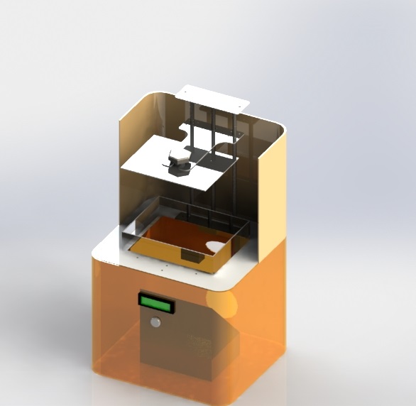
Initial render with all the component placed.
Manufacturing & Assembly
We did a tedious market research to find vendors for every component. We maintained their credentials and the cost of manufacturing in a sheet.

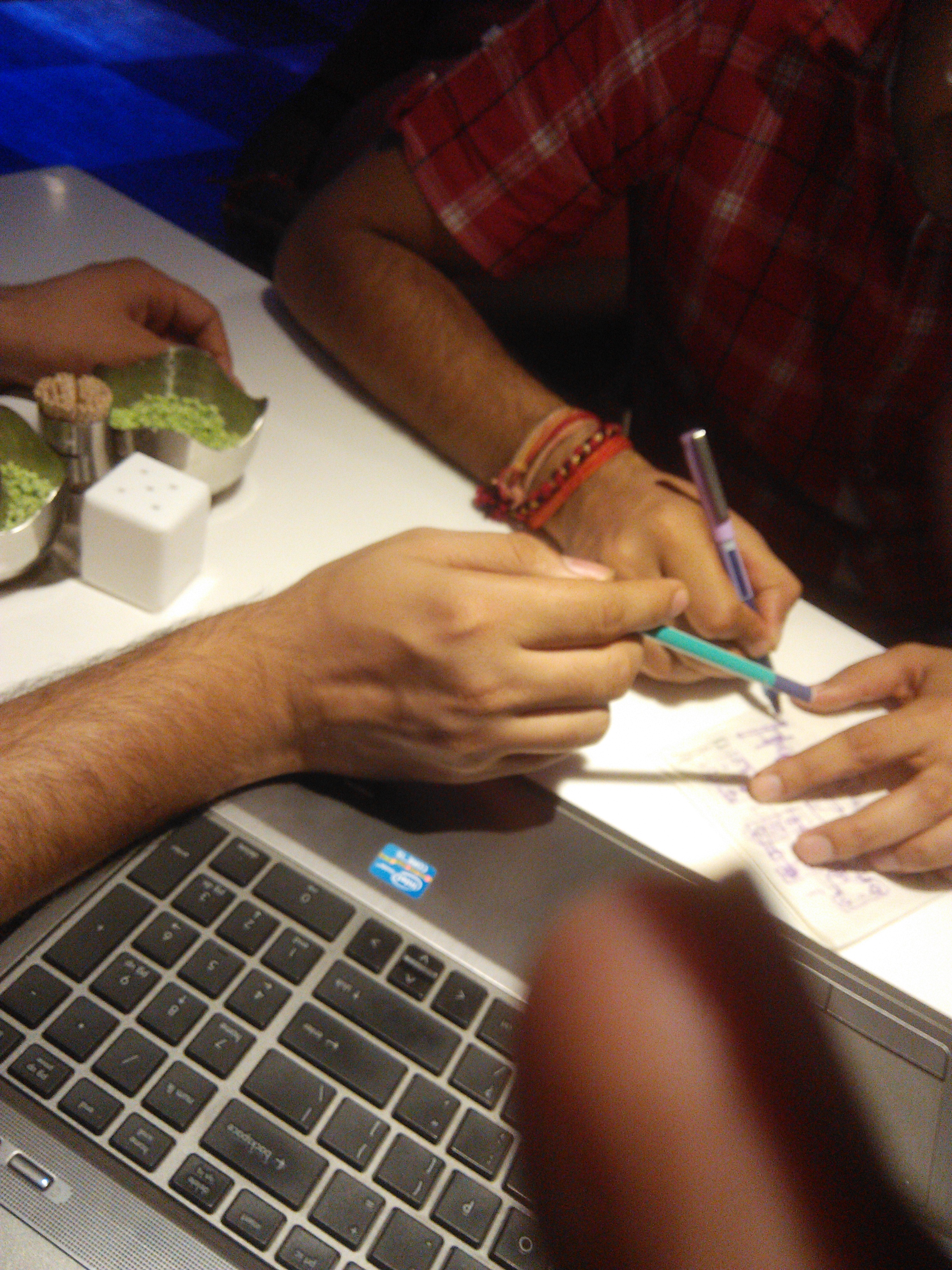
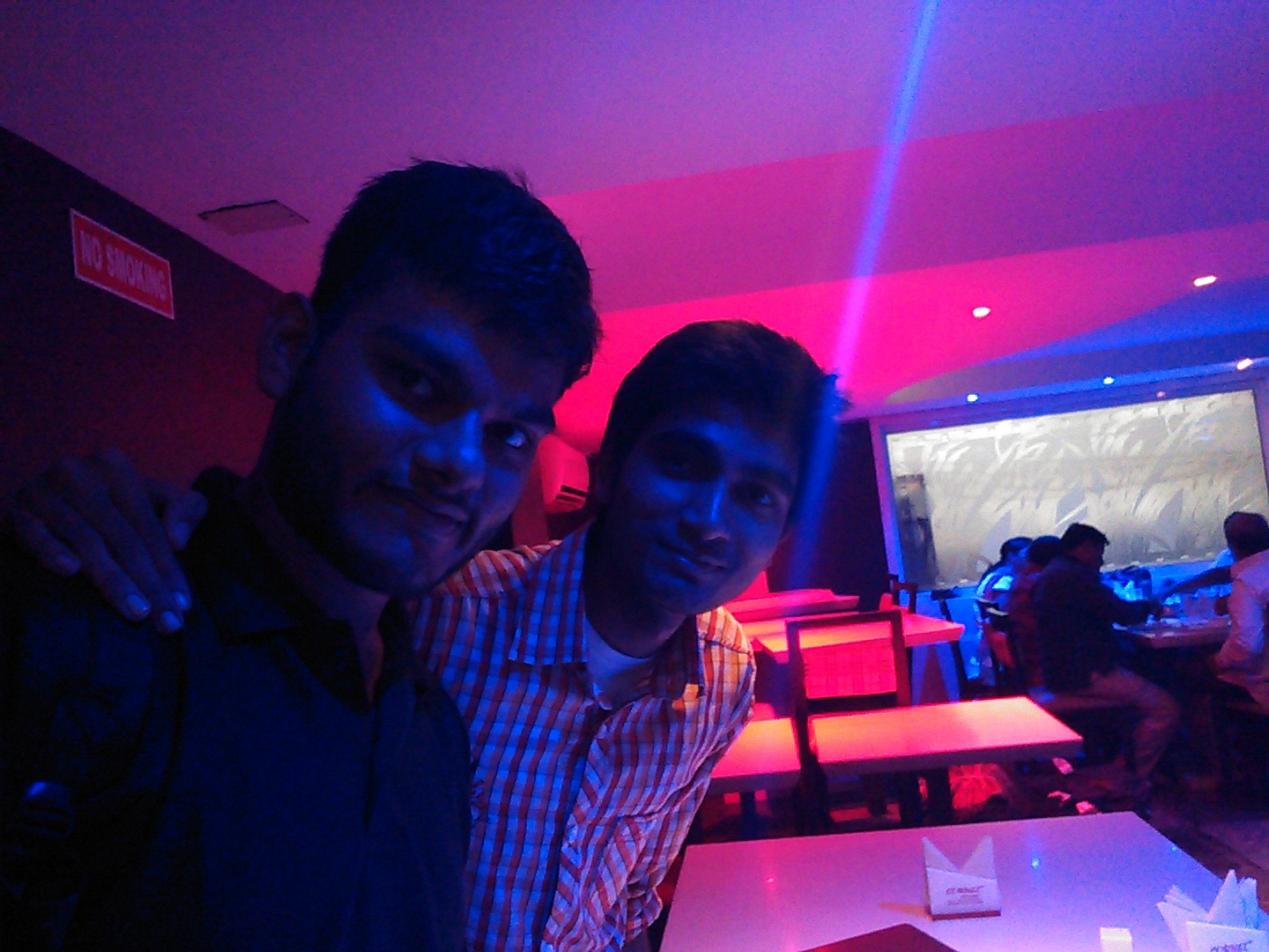
Here's us, discussing design modifications on a tissue paper in a restaurant when we went around market, searching for components.
System Design
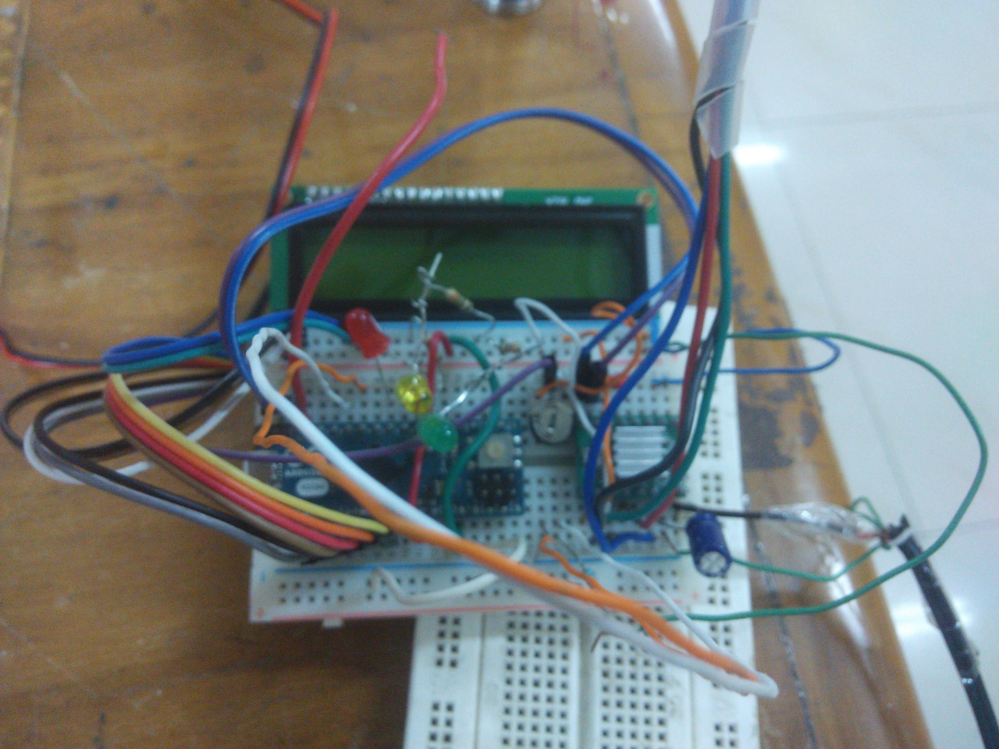
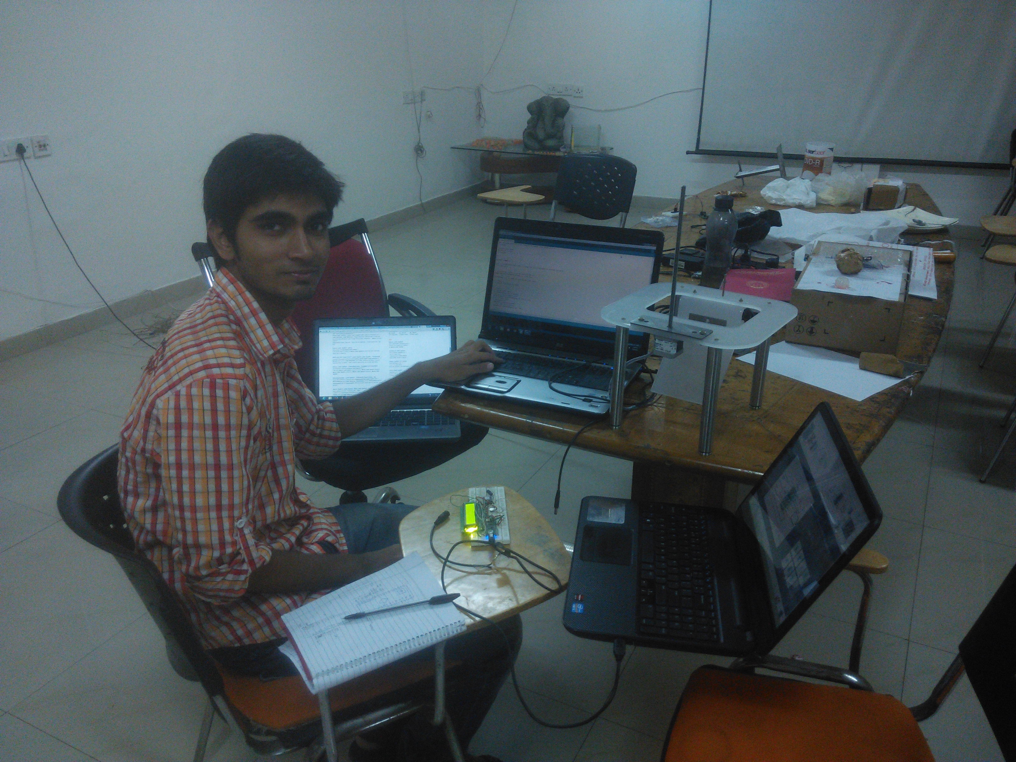
We would ultimately build our own PCB but for the general idea, here's how it looked on the breadboard -
Code
As said earlier, we wrote our own arduino code from scratch based on the specifications given above. For the logic, we determine the extreme positions with the help of limit switches. First, the base position is caliberated and then motor is sent the command after parsing G-code generated by Creation Workshop. The corresponding print time, remaining time and completion status are displayed on the LCD fitted outside. The entire code is in private domain, so I can't disclose the code according to the agreement.
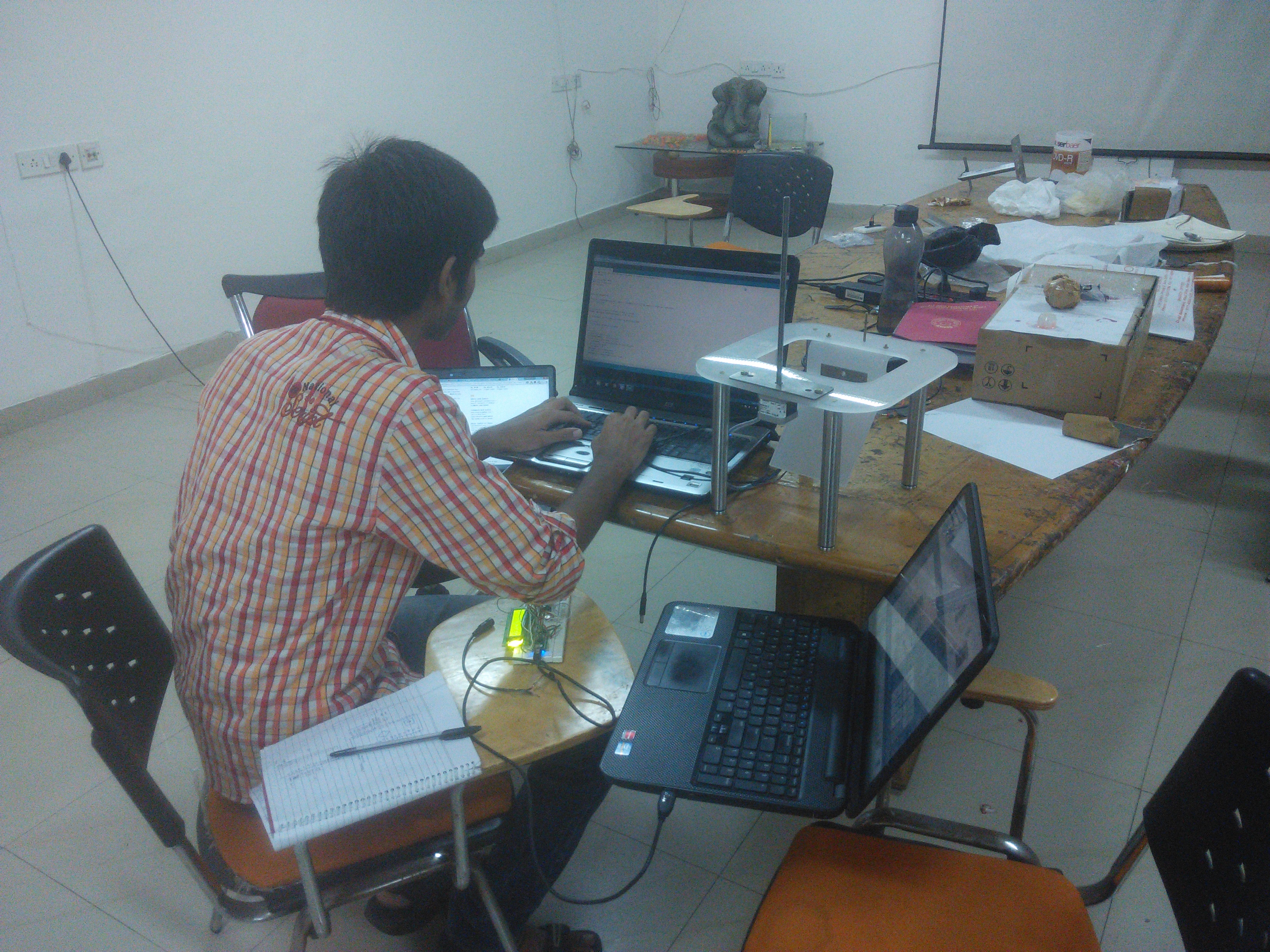
Here's me hacking that code :)
We encountered numerous problems along the way and I kept noting them in my diary. Here are some of the excerpts -
> Lack of hardener
> Liquid amount is crucial- when we're putting much liquid, the model is not getting formed while if we're putting less, then the base support is not getting enough liquid to print taking into
account the liquid suction due to vacuum formation.
Sheet transparency is also a probable problem. While going through some articles, we found that people were suggesting the change of sheets after 100000 or so layer prints. We can easily clear the glass but sheet cleaning might be tedious.
> Over-tightening may give rise of greater vacuum formation.
We increased the exposure time to 2s and moved it.
> Now we got the hardener OPV 7102. We started with mixing 5ml of it but to our utter surprise, the model was worse that the former with no hardener. In fact, the model didn't even complete because of the softness.
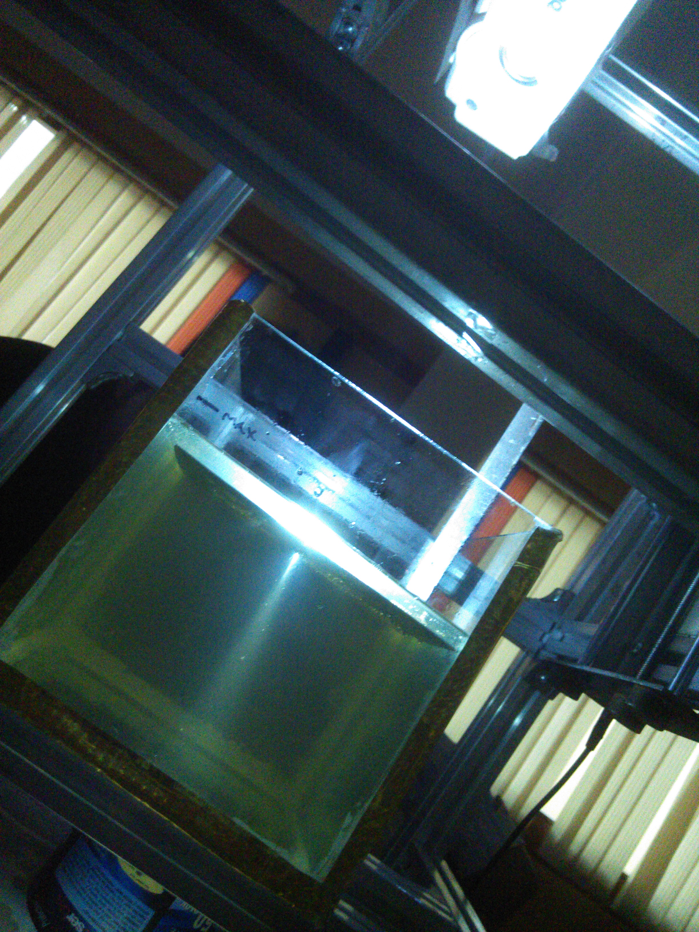
> Vacuum formation under the model - After switching to glass container, we faced a challenge of broken parts being printed out. It left us perplexed for a while. We looked for the cause by
eliminating the variable. After extensive research online, we finally identified the problem. It was the vacuum being formed at the base when hardened resin was being pulled out during
printing. Liquid resin couldn't fill it in time due to large adhesion with glass base. We tried differnt solution like coating the base with PDMS (polydimethylsiloxane) but the resin started
having whitish appearance at the bottom when heated. We had two other options - Sylgard 184 silicones or FEP sheets. Ultimately we decided to go with the later based on what people had
suggested. We designed the tension riser for the FEP sheets and we were able to print fine models afterwards.
The Glory
Finally, our 3D started coming together. We were also getting print of superior quality.
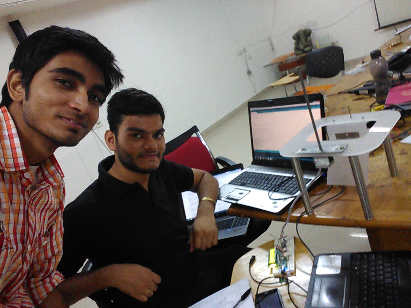
Miscellaneous Photos
All in all, it was a highly fulfilling experience. The learning I had in those one and half months far exceed one and half years of classroom education. We had our fair bit of fun in the process. Unfortunately, I had to leave before I completely assembled the product because of college. Besides work, an internship is also an excellent way to form a good friendship. Till the next time! Peace ✌